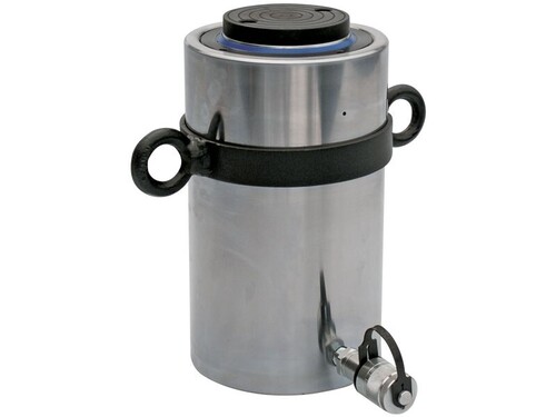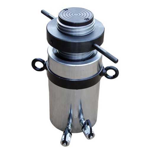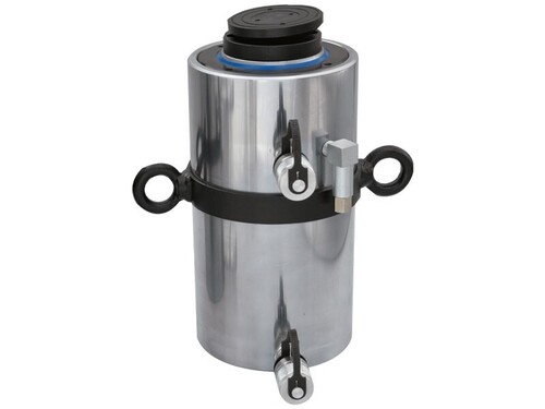


Hydraulic Cylinder Jack General Purpose Threaded Ram With Safety Lock Nut Single Acting Spring Return
Product Details:
- Temperature Range -20C to +60C
- Efficiency High Efficiency, Spring Return Design
- Features Safety Lock Nut, Threaded Ram, Corrosion Resistance, Overstroke Protection
- Application Lifting, Pushing, Lowering, Holding Loads in Construction, Maintenance, and Industrial Operations
- Mounting Type Base Mount or Side Mount Options
- Flow Rate Depends on Pump Used
- Operating Pressure 700 Bar (10,000 psi)
- Click to View more
Hydraulic Cylinder Jack General Purpose Threaded Ram With Safety Lock Nut Single Acting Spring Return Price And Quantity
- 1 Piece
- 20000 INR/Piece
- 15000.00 - 20000.00 INR/Piece
Hydraulic Cylinder Jack General Purpose Threaded Ram With Safety Lock Nut Single Acting Spring Return Product Specifications
- Hydraulic Coupler
- General Purpose Hydraulic Cylinder Jack
- Not Applicable (Manual Operation)
- High-strength Alloy Steel
- Hydraulic - Manual or Pump Driven
- Thread Protectors, Saddle, Coupler, Carry Handle
- 700 Bar (10,000 psi)
- Polyurethane and Nitrile Seals
- Depends on Pump Used
- High Efficiency, Spring Return Design
- -20C to +60C
- Base Mount or Side Mount Options
- 50 - 1000 tonnes (varies by model)
- Safety Lock Nut, Threaded Ram, Corrosion Resistance, Overstroke Protection
- Lifting, Pushing, Lowering, Holding Loads in Construction, Maintenance, and Industrial Operations
- Single Acting
- Threaded Ram with Safety Lock Nut
Product Description
| Capacity (ton) |
Capacity (kN) |
Stroke (mm) |
Model | Effective area (cm2) |
Oil cap. (cc) |
Closed height (mm) |
Wt. (Approx.) (kg) |
|---|---|---|---|---|---|---|---|
| 10 | 111 | 150 | OST 10-150 | 15.9 | 239 | 245 | 4.50 |
| 15 | 167 | 150 | OST 15-150 | 23.8 | 356 | 250 | 6.50 |
| 20 | 218 | 150 | OST 20-150 | 31.2 | 468 | 260 | 9.00 |
| 25 | 270 | 150 | OST 25-150 | 38.5 | 577 | 270 | 11.30 |
| 30 | 309 | 150 | OST 30-150 | 44.2 | 663 | 275 | 14.50 |
| 50 | 550 | 150 | OST 50-150 | 78.5 | 1178 | 290 | 26.50 |
| 75 | 792 | 150 | OST 75-150 | 113.1 | 1696 | 295 | 37.00 |
| 100 | 1077 | 150 | OST 100-150 | 153.9 | 2309 | 305 | 56.00 |
| 150 | 1589 | 150 | OST 150-150 | 227 | 3405 | 325 | 86.00 |
| 200 | 2199 | 150 | OST 200-150 | 314.2 | 4712 | 340 | 110.00 |
| 250 | 2661 | 150 | OST 250-150 | 380.1 | 5702 | 350 | 134.00 |
| 300 | 3167 | 150 | OST 300-150 | 452.4 | 6786 | 370 | 176.00 |
| 400 | 4008 | 150 | OST 400-150 | 572.6 | 8588 | 405 | 240.00 |
| 500 | 4948 | 150 | - | 706.86 | 10603 | - | 0.00 |
Features of General Purpose Jacks Threaded Ram
Some features and benefits of general purpose jacks threaded ram are:
- They have a high capacity ranging from 10 to 1000 tons and stroke lengths up to 300 mm.
- They have low height and compact design that makes them suitable for confined spaces.
- They have spherical saddles for larger capacities that can accommodate misalignment and angularity of loads.
- They have aluminum bodies for lighter weight and corrosion resistance.
- They have fast and complete ram retraction due to the spring return mechanism.
- They have double acting models that can extend and retract faster than single acting models.
Applications of General Purpose Jacks Threaded Ram
General purpose jacks threaded ram have various applications such as:
- Lifting and supporting heavy structures such as bridges, buildings, piles, beams, and columns
- Pushing and pulling machinery, equipment, vehicles, and tools
- Testing concrete strength, soil compaction, and pile integrity
- Aligning and leveling components during assembly or installation
- Clamping and pressing metal sheets, pipes, or tubes
Advantages of General Purpose Jacks Threaded Ram
General purpose jacks threaded ram have several advantages such as:
- High load capacity ranging from 10 to 1000 tons
- Long stroke length up to 300 mm
- High working pressure of up to 700 bar
- Durable construction with coated pistons to resist corrosion and abrasion
- Spherical saddle for better load distribution (optional for lower capacities)
- Fast and complete ram retraction
However, general purpose jacks threaded ram also have some limitations, such as:
- Limited side load capacity due to the thread design
- Need for regular lubrication of the threads to prevent wear and tear
- Risk of overloading or damaging the jack if not used properly
Safety Precautions
Therefore, it is essential to follow some safety precautions when using general purpose jacks threaded ram, such as:
- Always use a suitable pump with adequate pressure rating and flow rate
- Always use high-quality hydraulic oil with proper viscosity and cleanliness
- Always check the jack for any leaks, cracks, or damages before use
- Always use a flat and stable base to support the jack
- Always align the jack with the load axis to avoid bending or tilting
- Always use a gauge or indicator to monitor the pressure applied on the jack
- Always release the pressure gradually after completing the operation
Working Process of General Purpose Jacks Threaded Ram
General purpose jacks threaded ram are hydraulic devices that lift, push or pull heavy loads with high force. They have a threaded ram with a safety lock nut that can hold the load in place for a long time. They are used for various applications such as concrete pile testing, bridge support work, construction, and heavy industries.
The working process of general purpose jacks threaded ram can be outlined as follows:
1. The jack is connected to a hydraulic pump that supplies pressurized oil to the jack through a hose.
2. The pump is operated by an electric motor or a manual lever to generate the required pressure and flow rate of oil.
3. The oil enters the jack through an inlet port and pushes the piston inside the cylinder upwards.
4. The piston moves the ram upwards along with the load attached, utilizing a saddle or an adapter.
5. The ram has a thread on its outer surface that matches the thread on the lock nut inside the cylinder.
6. As the ram moves up, it rotates slightly and engages with the lock nut, which prevents it from sliding back down under gravity or external force.
7. The load is thus held securely by the jack in any position without any oil leakage or pressure loss.
8. To lower the load, the pump is reversed or stopped, and a release valve on the jack is opened to allow oil to flow back from the cylinder to the reservoir.
9. The piston moves down due to its weight and disengages from the lock nut, which rotates slightly and allows the ram to slide freely.
10. The load is lowered gradually by controlling the oil flow speed through the release valve until it reaches its desired position.
Robust Construction & Safety Features
This hydraulic jack utilizes a high-strength alloy steel cylinder and hard chrome plated ram, ensuring exceptional durability and resistance to industrial wear and corrosion. The integrated safety lock nut prevents accidental descent, delivering secure load holding even during extended operations. Designed with over-travel protection and pressure relief mechanisms, safety is enhanced for critical lifting and maintenance tasks.
Versatile Application & Mounting Options
Adaptable to diverse requirements, the jack supports multiple mounting options, including base and side mounting, and stroke lengths ranging from 250mm to 600mm. With a threaded ram and grooved, stable base plate, users can achieve precise positioning for lifting, pushing, lowering, or holding loads in construction, workshop, and heavy-duty industrial settings. Accessories like thread protectors and couplers further augment connectivity and protection.
FAQ's of Hydraulic Cylinder Jack General Purpose Threaded Ram With Safety Lock Nut Single Acting Spring Return:
Q: How does the safety lock nut enhance the security of load holding?
A: The safety lock nut mechanism allows the ram to be locked in position after lifting, preventing accidental descent and ensuring stable load holding during extended operations or maintenance tasks.Q: What are the benefits of the single acting spring return design?
A: Single acting spring return automatically retracts the ram when hydraulic pressure is released, streamlining usage and improving operational speed without manual intervention for return movement.Q: When should I select a specific ram stroke length for my application?
A: Ram stroke length should be chosen based on the required lifting height or travel. Projects needing higher elevation or deeper pushing can utilize models with longer stroke lengths, while compact operations may prefer shorter options.Q: Where can this hydraulic cylinder jack be installed or mounted?
A: It can be mounted using base or side mounting configurations, facilitated by precision machined collar threads and a grooved, stable base plate, making it suitable for installation in construction sites, manufacturing plants, and vehicle maintenance shops.Q: What maintenance process is recommended for reliable operation?
A: Routine inspection and timely replacement of seals-made from durable polyurethane and nitrile-will maintain hydraulic integrity. The designed industrial coatings and replaceable seals make maintenance straightforward and cost-effective.Q: What certifications and compliance does the product meet?
A: The hydraulic cylinder jack adheres to ISO 10100 standards, ensuring superior safety, reliability, and quality for use in industrial and construction sectors throughout India.
Price:
- 50
- 100
- 200
- 250
- 500
- 1000+

 Send Inquiry


